微通道流动沸腾不稳定性和临界热流密度特性研究
VIP免费
摘 要
微尺度条件下的沸腾换热与常规尺度传热有着显著的差异,随着现代科学技
术水平的不断提高,微型设备的散热要求越来越高,因此微尺度流动沸腾换热有
着广泛的应用前景,近年来已经成为国际传热学界研究的热点领域,本文对微细
通道内的流动沸腾不稳定性和 CHF 进行理论和实验研究,主要内容如下:
(1) 对微通道流动不稳定性进行实验研究,得出压降——流量特性曲线,该特
征曲线与理论分析完全吻合,都呈现“N”字形曲线,随着工质入口温度的升高,
压降——流量的“N”字形特性曲线变得越来越平坦,微通道中的沸腾不稳定性受
到抑制,气泡之间聚合演化形成的大气泡(其内部的压力较小)对微通道的阻力要小
于气泡急剧膨胀形成拉长气泡(其内部压力较大)对微通道的阻力。
(2) 发现去离子水为流动工质很容易发生不稳定性,且壁面温度波动振幅非常
大,而采用乙醇作为流动工质时,相对较难发生流动不稳定性,壁面温度波动的
振幅比较小。分析了壁温及压力周期性波动的振幅(壁面温度振幅达到 400 ℃)、周
期(10.5 s)、频率(0.095 Hz),发现壁温与压力同相位但与质量流量相位角几乎相差
180 度。随着入口过冷度的减小,流动沸腾不稳定性逐渐减小,当入口温度达到
80 ℃时,以去离子水为流动工质,几乎不发生沸腾不稳定性;相较于去离子水以
乙醇为工质时更不容易发生沸腾不稳定性。
(3) 微通道稳定沸腾区域和不稳定沸腾区域的划分,微通道内直径为 812.6 μm,
当去离子水入口温度为 23、40 ℃时,qeff/G=0.202、0.116 kJ/kg;微通道内径为 652.5
μm,当去离子水入口温度为 23、40 ℃时,qeff/G=0.321、0.192 kJ/kg。微通道直径
越大,从稳定沸腾区域过渡到不稳定沸腾区域的 qeff/G 值越小,说明微通道越大越
不容易发生流动沸腾不稳定性定。
(4) 分析微细通道轴向导热对流动沸腾过程的影响,根据 Maranzana 等研究人
员提出的分析计算微通道轴向导热能力的关联式,依据本实验条件参数计算平均
M=3.31×10⁻⁶ 远小于标准值 10-2,因此实验的分析计算中都不需要再考虑微通道轴
向导热的影响。
(5) 环状流阶段的 CHF,除了出口处热电偶 T7的温度很高外,其它位置的热
电偶温度都很低很均匀,但温度都高于对应压力下的饱和温度,这与环状流阶段
的以对流沸腾为主导的换热机制完全吻合。由于壁面的持续加热,沿流动方向环
状流型的液膜在蒸发作用下,液膜不断减薄最后出现局部干涸现象,从而触发了
环状流阶段的 CHF,在环状流与雾状流过渡的气、液、固三相接触线处的壁面得
不到新鲜液膜的润湿作用,此时就会出现相对较稳定的 CHF,此时的 CHF 值高于
不稳定沸腾阶段的 CHF 值。
(6) 在环状流型末端出现干涸时的气、液、固三相分界线处,建立表面张力、
惯性力、粘性力和蒸发动量力的力平衡关系式,即当蒸发动量力大于或等于表面
张力、惯性力和粘性力三项之和的时候,就认为在力的角度达到促发 CHF 的条件,
对该力的平衡关系进行处理得出了包含 We 数和 Ca 数的 CHF 关联式,最后经过实
验参数的回归分析得到该 CHF 关联式的系数值。
(7) 将实验参数代入根据力平衡原理得到的 CHF 关联式中,经过回归分析得
到系数值分别为 C1=3.6135×10⁻⁵,C2=-0.4908,C4=6.3155×10⁻⁴,所得关联式的预测
值都在±10%的偏差范围内,与实验数据吻合的良好。
关键词: 微细通道 流动沸腾 CHF 模型 不稳定性 液膜 干涸
力平衡原理
ABSTRACT
There are significant differences of boiling heat transfer. between micro-channels
and macro-channels. With the improvement of modern advanced technology, the
micro-device needs meeting the high demand of heat dissipation, thus flow boiling
heat transfer in micro-channels has extensive applied prospect. Flow boiling heat
transfer in micro-channels already becomes a hot academic field in the international
heat transfer society. Experimental and theory study on instability and critical heat
flux of flow boiling in micro-channels have been done in this paper. The main
contents of this paper are as following:
(1) Research the experiment of flow boiling instability in micro-channels, and
obtain the character curve of pressure-drop—mass flux which agrees well with
theoretical analysis and the curve appears the shape of “N”. The shape of character
curve of pressure-drop—mass flux becomes more and more smooth and the instability
of flow boiling in micro-channels is restrained with the inlet temperature of working
medium increasing. The resistance of flow of big bubbles (the inner pressure of
bubbles is small) which comes from evolution between bubbles is smaller than that of
elongated bubbles (the inner pressure of bubbles is large) through rapid explode.
(2) Finding the working medium instability occurs easily and the amplitude of
temperature of micro-channel’s wall is very large when the working medium is
deionized water. While the flow boiling instability occurs scarcely and the amplitude
of temperature of micro-channel’s wall is small when the alcohol is as working
medium. Analyze the periodic amplitude (when the amplitude of wall temperature
reaches 400 ℃) and period(10.5 s) and frequency(0.095Hz) of wall temperature and
pressure oscillation. Find that the wall temperature and pressure are in the same phase
but the phase angle is almost different from the mass flux and the phase differ 180
degrees. The flow boiling instability gradually became small with the inlet condensate
depression decreasing. Using deionized water as working medium ,we find that the
flow boiling instability almost didn’t appear when the inlet temperature reaches
80 ℃.Compared with deionized water , using the alcohol as working medium , flow
boiling instability hardly occur.
(3) Divide the stable boiling region of the micro-channel and unstable boiling
region. When the inner diameter of micro-channel is 812.6μm and inlet temperature of
deionized water are 23 and 40 °C respectively, qeff/G =0.202 and 0.116 kJ/kg; While
the inner diameter of micro-channel is 652.5 μm and the inlet temperature of
deionized water are 23 and 40 °C respectively, qeff/G= 0.321 and 0.192 kJ/kg. The
larger the diameter of the micro-channel, the transition from stable boiling region to
unstable boiling region qeff/G value is smaller, and the larger the micro-channel is, the
less possibility of flow boiling instability to occur.
(4) Analyze the impact of axial thermal conductivity in the micro-channel on the
flow boiling process. According to the axial heat conduction capability correlation of
micro-channels proposed by researchers such as Maranzana, based on the parameters
of the experimental conditions, calculate the average M=3.31×10⁻⁶ ,and it is far
smaller than the standard value of 10-2, the impacts of micro-channel axial heat
conduction are not considered in the experimental analysis calculations.
(5) When CHF is in annular flow, in addition to the outlet from the high
temperature of the thermocouple T7 at this stage, the other position of the
thermocouple temperature is low and uniformly, but the temperature is higher than the
saturation temperature corresponding to the pressure, which is consistent to heat
transfer mechanism led by convection boiling in annular flow stage. Due to the
continued heating of the wall surface, the liquid film along the direction of flow of the
annular flow in the evaporation effect, the film constantly last thin and partly dry up,
thereby triggering the critical heat flux(CHF) of annular flow stage, in the annular
flow and the mist flow transition stage the gas, liquid, solid three-phase contact line at
the wall is not the role of fresh liquid film wetting appears relatively stable CHF, the
CHF value in annular stage higher than that in the unstable boiling stage.
(6) At the three phases boundary line of gas, liquid, solid in the end of the
annular flow, establish the force balance relationship of surface tension, the force of
inertial force, the viscous force and evaporated momentum force, i.e. when the
evaporation momentum force is greater than or be equal to the sum of the surface
tension, inertial forces and viscous forces when considered reaching the priming
conditions of CHF in the angle of the force, and processing the force equilibrium
relationship obtained the CHF correlation which contained We number and Ca number,
and finally the coefficient values of the CHF correlation obtained through regression
analysis of the experimental parameters.
(7) Substitute the experimental parameters into CHF correlation obtained
according to the force balance principle ,the coefficient values were obtained by
regression analysis that C1=3.6135×10⁻⁵, C2=-0.4908, C4=6.3155×10⁻⁴, the resulting of
the correlation predictive value are within the deviation range of ±10%,and the results
coincide well with experimental data.
Key words: micro-channels, flow boiling, critical heat flux, model,
instability, liquid film, dry-out, force balance principle
目 录
中文摘要
ABSTRACT
第一章 绪 论………………………………………………………………………….1
§1.1 课题背景及意义 ............................................................................................ 1
§1.2 通道划分标准 ................................................................................................ 1
§1.3 微细通道内的流动沸腾 ................................................................................ 3
§1.3.1 微细通道内的沸腾起始点 .................................................................... 3
§1.3.2 微细通道内的流动沸腾不稳定性 ........................................................ 4
§1.3.3 微细通道内的流动沸腾换热特点 ........................................................ 4
§1.4 国内外对微细通道 CHF 的研究现状 .......................................................... 6
§1.4.1 通道内 CHF 的分类 .............................................................................. 6
§1.4.2 国内外对微细通道 CHF 的实验研究 .................................................. 7
§1.4.3 微细通道 CHF 的经验关联式 ............................................................ 10
§1.4.4 微细通道 CHF 的理论模型 ................................................................. 11
§1.5 本课题研究内容及工作 .............................................................................. 12
第二章 微细通道流动沸腾实验装置系统…………………………………………...13
§2.1 实验目的和内容 .......................................................................................... 13
§2.2 实验装置系统 .............................................................................................. 13
§2.3 实验段 .......................................................................................................... 15
§2.4 测量方法 ...................................................................................................... 18
§2.4.1 温度测量 .............................................................................................. 18
§2.4.2 压力测量 .............................................................................................. 19
§2.4.3 加热功率 .............................................................................................. 19
§2.4.4 质量流量 .............................................................................................. 19
§2.4.5 数据采集 .............................................................................................. 20
§2.5 实验操作步骤 .............................................................................................. 20
§2.6 实验数据处理 .............................................................................................. 21
§2.7 不确定度分析 .............................................................................................. 23
§2.8 本章小结 ...................................................................................................... 24
第三章 流动沸腾不稳定性研究……………………………………………………...25
§3.1 微通道内的沸腾不稳定性特征 .................................................................. 25
§3.1.1 微通道内的静态不稳定性特征 .......................................................... 25
§3.1.2 微通道内的动态不稳定性特征 .......................................................... 25
§3.1.3 微通道内部流动系统压力的研究 ...................................................... 25
§3.1.4 微通道流动系统外部驱动压力的研究 .............................................. 28
§3.2 微通道内沸腾不稳定性特征实验 .............................................................. 29
§3.2.1 微通道内压降——流量特征曲线 ...................................................... 29
§3.2.2 微通道内温度压力流量的不稳定性 .................................................. 34
§3.2.3 稳定沸腾区和不稳定沸腾区的划分 .................................................. 43
§3.3 本章小结 ...................................................................................................... 48
第四章 微细通道内 CHF实验研究…………………………………………………..50
§4.1 微细通道轴向导热分析 .............................................................................. 50
§4.2 微细通道内不同条件下两种 CHF 的壁温分布特点 ................................ 50
§4.2.1 微细通道内不稳定沸腾阶段的 CHF 的壁温分布 ............................ 50
§4.2.2 微细通道内环状流阶段 CHF 的壁温分布 ........................................ 52
§4.3 微细通道 CHF 与壁面过热度的关系 ........................................................ 53
§4.4 微细通道 CHF 与干度的关系 .................................................................... 56
§4.5 微细通道 CHF 与各种 CHF 关联式预测值的比较 ................................... 57
§4.6 本章小结 ...................................................................................................... 59
第五章 微细通道 CHF模型研究……………………………………………………..61
§5.1 建立微细通道流动沸腾 CHF 模型的基本条件 ........................................ 61
§5 .1.1 建立微细通道 CHF 模型的前提 ........................................................ 61
§5.1.2 建立微细通道 CHF 模型的基本假设 ................................................ 62
§5.1.3 微细通道内各种作用力的研究 .......................................................... 62
§5.2 建立微细通道流动沸腾 CHF 模型 ............................................................ 66
§5.2.1 微细通道 CHF 模型的无量纲数组 .................................................... 66
§5.2.2 微细通道 CHF 模型的受力分析 ........................................................ 67
§5.2.3 微细通道 CHF 模型中接触角的分析 ................................................ 70
§5.3 微细通道 CHF 与模型预测关联式的关系 ................................................ 71
§5.4 本章小结 ...................................................................................................... 72
第六章 总 结………………………………………………………………………...74
§6.1 研究内容总结 .............................................................................................. 74
§6.2 研究展望 ...................................................................................................... 75
附 录A……………………………………………………………………………….77
附 录B……………………………………………………………………………….78
参考文献……………………………………………………………………………….81
在读期间公开发表论文和承担科研项目及取得成果……………………………….88
致 谢………………………………………………………………………………….89

第一章 绪 论
1
第一章 绪 论
§1.1 课题背景及意义
近些年来,微处理器和电子设备产业面临着热流密度高达 1000 W/cm2甚至更
高热负荷的挑战,同时又要求设备的温度维持在比较低的范围内。虽然传统的冷
却方法在一定条件下得到了成功的应用,如空气冷却热沉,但是这种冷却方式却
不能满足高热流密度设备的使用条件[1]。其它的冷却方法,如:喷射冷却、微通道
内的单相和两相流动沸腾冷却,已经得到广泛的应用,并表现出传统冷却方式不
具备的很多优点[2,3,4],在各种冷却方式中,微通道内两相流动沸腾是一种非常有效
的冷却方式。由于互联网的迅速扩张,数据中心的数据交换处理所消耗的能量急
剧增加,各种电子设备消耗的电能所占的比例越来越大,节能势在必行,因为微
通道中的两相冷却是非常高效的换热方式,它降低了设备潜在的能量消耗,然而
为了确定电子设备安全操作的限制条件和最大的热消耗功率,需要对微通道内流
动沸腾的 CHF(critical heat flux)有全面深入的认识。目前,文献中有大量关于宏观
尺度体系如核电站的 CHF 实验数据[5,6],这些 CHF 数据中又以常规圆形管道的研
究为主,然而文献中有关微通道流动沸腾 CHF 的实验数据非常有限,通常在这些
实验中主要以制冷剂作为流动工质。Celate 等[7]和Katto[8]对过冷沸腾 CHF 的研究
进行了广泛的整合与总结。对于电脑芯片冷却,由于实际条件的限制,中等压力
下冷却的效果非常好,此外在小通道内,入口处的过冷度比较小,质量流量相对
较低时所需要的泵功率也很小,因此在这些流动条件下都认为是饱和 CHF。基于
单根圆形大通道的宏观尺度方法不能用于预测具有饱和出口条件的微细矩形多通
道的 CHF[9,10]。现阶段对常规通道内的流动沸腾有了比较深入的实验研究,积累了
大量实验数据,根据这些实验数据和影响因数,建立相应的几何模型,提出了很
多实验及经验关联式,但遗憾的是绝大多数常规通道关联式不能用于预测微细通
道内的流动沸腾换热,必须根据微细通道流动沸腾的特点,用实验数据对相关关
联式进行修正,甚至提出微细通道流动沸腾换热模型,从理论上推导出微细通道
沸腾换热关联式,现在严重缺乏微细通道流动沸腾换热各个领域的实验数据,需
要研究人员进行深入的研究和分析。
§1.2 通道划分标准
众所周知,当通道尺寸小到一定程度之后,通道内流体的流动和换热会发生
尺度效应,“微细”只是一个相对的概念,小到什么程度才能称为微细,依赖于具
体的物理过程,国际上众多学者提出多种划分常规通道、细通道和微通道的标准,
根据不同的机理主要分为如下几类:
(1) Mehendale 等[11]和Kandlikar[12]基于实际工程应用,提出以水力直径大小作为通

微细通道流动沸腾不稳定性和临界热流密度特性研究
2
道划分标准,如表 1-1 所示。
表 1-1 通道划分标准
分 类
Mehendale 等[11]
Kandlikar[12]
常规通道
Dh>6 mm
Dh>3 mm
细通道
100 μm<Dh<6 mm
200 μm<Dh<3 mm
微通道
1 μm<Dh<100 μm
10 μm <Dh<200 μm
(2) 基于气泡在通道中生长会受到壁面的限制作用,Kew 和Cornwell[13]提出以受限
数Co 作为划分标准,Co<0.5 是常规通道,Co>0.5 是微通道。
(3) 根据物理机制差异,Cheng 和Wu[14]用Bond 数作为通道划分标准,表 1-2 所示。
表 1-2 Bond 数作为通道划分标准
分 类
Bond 数
备注
常规通道
Bond>3.0
重力起主导作用
细通道
0.05<Bond<3.0
表面力起主导作用
微通道
Bond<0.05
忽略重力的影响
(4) 根据核态沸腾气泡核化所需的最小临界成核半径,Lin 和Pisano[15]提出划分标
准。
(5) 在微通道的某一横截面处只允许有一个气泡存在,基于气泡的脱离直径,
Thome[16]提出以池沸腾气泡脱离直径作为划分标准,Fritz[17]的气泡脱离直径计算
公式如下:
即: ,对于高压条件,公式修正为:
(6) Li 和Wu[18]经过分析通道内的重力、惯性力、表面张力和粘性力的大小关系,
提出以邦德数 Bo 和雷诺数 Re 组合的无量纲数作为通道的划分标准,当 Bo
·
Re0.5
大于 200 时为常规通道,Bo
·
Re0.5 小于等于 200 时为微通道。
很显然,第一种粗略划分标准过于武断,完全不能体现出流体与通道之间各
种物理机制的相互关系,如气泡与通道之间的限制关系,更不能够体现出经典理
论不能够适用于微通道的范围,所以划分标准必须要考虑流体的性质,上述后面

第一章 绪 论
3
几种通道划分标准更切合实际更科学更合理。
流动沸腾换热与气液界面存在密切相关,其中作用力包括惯性力、表面张力、
切应力和蒸发动量力,随着管径的减小,各种力的绝对梯度都减小,而相对梯度
如何变化决定了微小尺度的划分。Kandlikar[19,20]根据微小通道内不同受力情况提
出了两个无量纲参数表示尺度效应:
其中 K1包含了 Bo 数和气液密度比,Bo 数并不代表蒸发动量而 Bo 数结合气
液密度比则代表了蒸发动量力,K1值越大蒸发动量力越大,界面运动改变越大;
K2表示蒸发动量力与表面张力的比值,其中并不包含接触角,蒸发动量力越大界
面越易克服表面张力,K2控制了接触线上的界面运动。
§1.3 微细通道内的流动沸腾
§1.3.1 微细通道内的沸腾起始点
现在一个特别重要的研究课题是微通道内核态沸腾起始点(onset of nucleate
boiling)的预测,核态沸腾起始点是区分单相与两相流动的分界点,发生 ONB 时压
降突然急剧增大,质量流量降低,换热能力突然增强,使得微通道壁面温度降低,
并基本保持稳定不再线性增加。沸腾起始点的确定方法大致可以分为以下四种:
直接标定法、确定单相对流换热段曲线与过冷沸腾换热段曲线的交点、壁面温度
线性增加到突然降低的转变点、质量流量突然降低或压降突然增加的点。ONB 的
预测需要充分理解 OSV(onset of significant void)和DNB(departure from nucleate
boiling)等流动沸腾现象[21]。Hsu[22]最先假设池沸腾中 ONB 的最小过热度标准,他
提出只有气泡周围(气泡顶部)的最小温度大于或等于气泡内蒸汽的饱和温度时,核
化气泡才能生长。国际上很多学者对 ONB 的研究都是基于 Hsu[22]的这个基本假设
为前提条件,如 Bergles 和Rohsenow[23]扩大了 Hsu[22]的模型,提出了预测流动沸
腾初始热流密度的图解法;Sato 和Matsumara[24]根据壁面温度推导出了初始热流密
度的分析关系;Davis 和Anderson[25]提出了 Bergles 和Rohsenow[23]方法的分析处
理,引入接触角作为 ONB 预测的变量。
Liu 和Lee 等[26]研究了微通道热沉中水流动沸腾起始点,微通道宽 275 μm深
636 μm,用高速摄像仪识别了 ONB,测量各种流动条件下初始热流密度值,提出
一个分析模型来预测初始热流密度大小和沸腾起始时的气泡尺寸,所获得方程的
封闭解解释了重要的系统参量对初始热流密度的影响,模型与实验数据符合的非
常好。

相关推荐
-
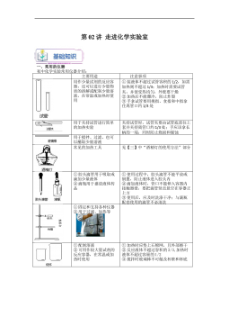
上海沪教版新九年级化学暑假同步课_走进化学实验室(教师版)VIP免费
 2024-09-26 13
 -
上海沪教版新九年级化学暑假同步课_质量守恒定律(学生版)VIP免费
 2024-09-26 12
 -
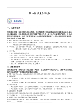
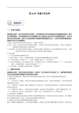
上海沪教版新九年级化学暑假同步课_质量守恒定律(教师版)VIP免费
 2024-09-26 14
 -
上海沪教版新九年级化学暑假同步课_氧气的制取(学生版)VIP免费
 2024-09-26 14
 -
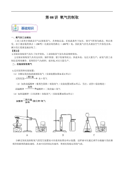
上海沪教版新九年级化学暑假同步课_氧气的制取(教师版)VIP免费
 2024-09-26 13
 -
上海沪教版新九年级化学暑假同步课_暑假预习成果卷(测试范围:第1-2章)(学生版)VIP免费
 2024-09-26 12
 -
上海沪教版新九年级化学暑假同步课_暑假预习成果卷(测试范围:第1-2章)(教师版)VIP免费
 2024-09-26 11
 -
上海沪教版新九年级化学暑假同步课_世界通用化学语言(学生版)VIP免费
 2024-09-26 13
 -
上海沪教版新九年级化学暑假同步课_世界通用化学语言(教师版)VIP免费
 2024-09-26 13
 -
上海沪教版新九年级化学暑假同步课_人类赖以生存的空气(学生版)VIP免费
 2024-09-26 15
作者:赵德峰
分类:高等教育资料
价格:15积分
属性:94 页
大小:4.32MB
格式:PDF
时间:2025-01-09
作者详情
相关内容
-
上海沪教版九年级化学上册暑假班课后练习(机构)_溶液的基本概念
分类:中小学教育资料
时间:2024-09-27
标签:无
格式:DOC
价格:5 积分
-
上海沪教版九年级化学上册暑假班课后练习(机构)_神奇的氧气
分类:中小学教育资料
时间:2024-09-27
标签:无
格式:DOC
价格:5 积分
-
上海沪教版九年级化学上册暑假班课后练习(机构)_世界通用的化学语言
分类:中小学教育资料
时间:2024-09-27
标签:无
格式:DOC
价格:5 积分
-
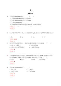
上海沪教版九年级化学上册暑假班课后练习(机构)_水
分类:中小学教育资料
时间:2024-09-27
标签:无
格式:DOC
价格:5 积分
-
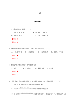
上海沪教版九年级化学上册暑假班课后练习(机构)-碳
分类:中小学教育资料
时间:2024-09-27
标签:无
格式:DOCX
价格:5 积分